
God day!!!
Just want to apologize for my English. I am from Belarus and if there are errors, then feel free to write about them, I will correct them :).Not so time ago, I faced with the need to work with the Frame Relay network. I have looked some guide and find that in GNS3 have Frame Relay switch.
Who want to know how install and configure him – welcome to post!!!
Run GNS3. Add one frame relay switch to working place (from left menu) and three routers (I choose cisco 2961) for future tests. If you don’t know how to add devices in GNS3 you may look this post. In the end you will have this scheme:

If you now try to connect routers directly to the switch, then will not work. Let’s fix this.
Click right mouse button on switch and go to "configuration" from drop down menu. Choose our device and you must see something like this:

Now we must to fink about how many ports we need and what links between routers we will be configure. For each link we must choose DLCI (Data Link Connection Identifier) and prescribe them to match the switch.
Let’s define what DLCI will be between all routers. Create this table:
- R1--R2 – DLCI 52
- R1--R3 – DLCI 53
- R2--R1 – DLCI 25
- R2--R3 – DLCI 23
- R3--R1 – DLCI 35
- R3--R2 – DLCI 32
Come back to configuration Frame Relay switch. For adding link you must choose pair source-port with source-DLCI and destination-port with destination-DLCI. Click «Add» and this pair appear, like on next picture:

Make this configuration for all of our relationships in the table (note that in the table we have indicated all the possible connections, but when you add them will need only three matches, because we indicated at once the source and destination).
The final table of the switch should look like this:

Click «Apply» and then «OK».
After that you may add links between routers and Frame Relay switch. The final scheme for further adjustments should be like this:
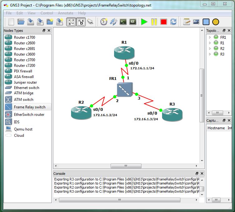
Now let’s configure our routers (IP-addresses for routers you can see in the top picture).
Router R1:
R1>en

R1#conf t

R1(config)#int serial 0/0

R1(config-if)#ip address 172.16.1.1 255.255.255.0

R1(config-if)#encapsulation frame-relay – turn on frame-relay encapsulation on interface;

R1(config-if)#frame-relay map ip 172.16.1.2 52 – define correspondence between the IP and DLCI;

R1(config-if)#frame-relay map ip 172.16.1.3 53

R1(config-if)#no shutdown

R1(config-if)#exit

R1(config)#exit

R1#wr

R1#
Router R2:
R2>en

R2#conf t

R2(config)#int serial 0/0

R2(config-if)#ip address 172.16.1.2 255.255.255.0

R2(config-if)#encapsulation frame-relay

R2(config-if)#frame-relay map ip 172.16.1.1 25

R2(config-if)#frame-relay map ip 172.16.1.3 23

R2(config-if)#no shutdown

R2(config-if)#exit

R2(config)#exit

R2#wr

R2#
Router R3:
R3>en

R3#conf t

R3(config)#int serial 0/0

R3(config-if)#ip address 172.16.1.3 255.255.255.0

R3(config-if)#encapsulation frame-relay

R3(config-if)#frame-relay map ip 172.16.1.1 35

R3(config-if)#frame-relay map ip 172.16.1.2 32

R3(config-if)#no shutdown

R3(config-if)#exit

R3(config)#exit

R3#wr

R3#
Well, everything should work :). Let's go back to the routers, try to execute ping command and check what we have.
Router R1:

Router R2:

Router R3:

As you can see, all we have works. I congratulate you!!!
On this, I want to finish this post. I hope he was informative for you and I want to thank you for your attention.
If you have a questions or comments, then do not be afraid to write me!!!! This is my contact information. I will pleased to answer!!!!
I’m waiting for you in next posts!!!
With best regards, Ant0ni0n
Have any Syslog messages related to FrameRelay Failures.
ReplyDeleteThank You Sir :)
ReplyDeletetnx man, much appreciated
ReplyDeletebundle of thnx sir
ReplyDeletegracias, muchas gracias
ReplyDelete